Buttress Stabilization – Part II
This is part two of a four-part series on buttress stabilization equipment and techniques. In the last segment we discussed equipment selection criteria and defined the 3-point stabilization technique for buttress stabilization of a side-resting passenger vehicle. In this segment we discuss buttress end fittings, base restraints, and various accessories which will aid in the stabilization process.
End Fitting Selection
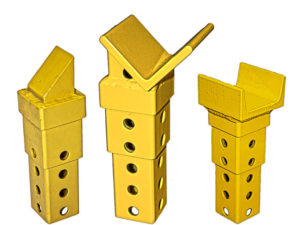
The prop tips must engage the vehicle in a manner in which they will not slip or otherwise surprise the rescue team. A system with interchangeable heads offers the flexibility to deal with various structures. For example, to make a purchase at the base of a roof post, the end fitting should cradle the post. To engage an outside corner, an angular fitting may be appropriate. For an inside corner, one may prefer to use a pointed fitting.
Tip contact points must be carefully selected to avoid the necessity to relocate a prop during the operation. Look for structurally sound areas. On the passenger compartment side of the vehicle a purchase point may be gained at the base of the ‘A’ and rear roof posts. Alternatively, the corner of the hood or trunk near the passenger compartment may be peeled back to gain a purchase. Some situations may require cutting a panel to gain adequate purchase as a last resort. Pockets such as gas fill compartments or exterior lighting cutouts in the fenders may provide adequate purchase points. The undercarriage side of the vehicle typically offers plenty of options such as the rolled lip found on most vehicles below the “rocker” panel, or a bend in the floor pan.
Base Construction and Restraint Considerations
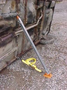
It is imperative that the base of the prop be restrained from movement. The base of the prop must be restrained from slipping out away from the vehicle. This is accomplished in various ways. The bases may be secured to the surface where they rest, or better yet tied back to the vehicle via strapping or chain of appropriate strength, or both tied and secured to the surface. The base restraints should be attached to the vehicle as near ground level as possible.
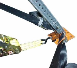 Use at least two straps at each base unless this is impractical. Using two straps allows the strap connection with the vehicle to be independent of the tip contact point. Typically, when using a single ratchet strap, for example, you need to ensure that you have a strap connection with the vehicle directly beneath the prop tip purchase. If not, tightening the strap may pull the base sideways and possibly cause the stand to topple. With two straps, the process is less restricted. In this case, the placement of the tip has less of an impact on strap connection. Ideally, the two straps would angle out from the base to the vehicle, and not necessarily at the same angle. Select an angle between the two straps of 45 to 90 degrees. The greater the angle between the straps the greater the load on the strap. This strap configuration restricts both outward and side-ward movement of the base. Note that in some instances, the best or only strap purchase is straight back to the vehicle. In this case, you should still connect both straps.
The base shown here has two cam-buckle straps pre-connected. This type of strap offers a quick means of adjusting. To adjust these straps, you merely pull the slack out by hand. The cam-buckle will not allow the strap to return without pushing the cam lever. This type of strap requires the use of a system with a tightening or fine adjusting mechanism such as the side-wind jack unit in the Res-Q-JackTM system as you can only hand tighten a cam-buckle strap. The jack accomplishes the final strap tightening in all stands assuming the stand with the jack is opposite and between the two stands without the jack. This avoids the need to use a ratchet strap which, for some, can be a battle or at least time consuming. If, however, the system is setup in the absence of a tightening mechanism such as the jack unit, or it is setup in a fashion in which the jack unit will not appropriately tighten a stand’s strapping, a ratchet strap may be applied at the center of the base, and the cam-buckle straps can simply serve as redundant restraints or added security. Whatever system you choose to use, be sure it offers the type of flexibility discussed here to meet whatever situation you may face.
Several charts in another segment of this article will give approximate tension forces experienced by base strapping for various column loads, column angles, and strapping configurations. You will see a chart for single, double, and triple strap bases. The formulas used assume that the ground is frictionless which simply means that the straps will be responsible for handling all the force required to keep the base from sliding or kicking out. This is a good assumption for those of us that deal with ice. A diagram of the Res-Q-Jack base is used to identify the parameters and load designations.

 Strapping Accessories
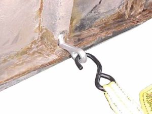
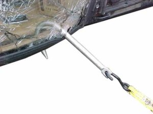
Many straps use ‘S’ hooks as a means of attaching to the vehicle. These should usually work fine. A suitable place on the vehicle to connect the strap may be hard to find at times. Strap hooks may not fit into some frame slots, which would otherwise make a great purchase location. In addition, an object may be too large to grab with the strap hook, such as a roof post. Wrapping the strap around roof posts, can expose the strap’s webbing to sharp glass or metal which is undesirable. T-hooks, and J-hooks circumvent these problems, and further speed up the stabilization process. T-hooks become an interface between many frame slots and the strap hook. J-hooks are simply large hooks which will readily grab a roof post, frame member, or similar.
Ground Surface Considerations
The type and condition of the surface the vehicle is resting on is also an important factor in stabilization. If the surface is inclined, a 3-point prop may not be sufficient. It may be necessary to incorporate additional means of securing the vehicle from sliding depending on the situation. Some prop systems may be impaired by soft ground. It may be necessary to use wide rigid pads beneath the prop base to avoid point loading. You may need an entirely different means of stabilizing.
Never Ending Operation
Stabilization goes on through the operation. At a Firehouse Expo class, Ron Moore put it nicely when he said, “stabilization is one assignment that never ends during an MVA operation”. The characteristics of the wrecked vehicle change during an extrication. The car’s weight changes and its center of gravity shifts as rescuers and equipment are added or as vehicle components are removed. The already compromised structural integrity of the vehicle is altered as doors are removed, a roof post is cut, or as glass is fractured. The roof and posts of a vehicle are effectively a truss. Removing them significantly reduces the stiffness of the vehicle. During a vehicle rescue incident, the stabilization components must be monitored. Base restraints may need adjusting, purchase points may have to be altered, and additional stabilization materials may be added. Those operating cutting tools must be aware of the effect they will have on the stabilization, and they must be careful not to remove a member which is engaged by a prop or base strap. A team member must be designated to monitor the stabilization components and make others aware of potential problems.
Basic Guidelines
Here are some basic guidelines for stabilizing the side-resting car on flat ground:
- Manually stabilize and/or place wedges to control vehicle while setting up buttress system.
- Based on situation, location of patient, type and condition of vehicle, and any obstructions, determine which side of vehicle to place single jack stand, and which side to place the two adjustable stands if using a 3-point setup.
- Work in a two-person team. One team member will watch for trouble within arm’s length of member adjusting and setting stands.
- Set stand(s) on least stable side of vehicle first, then work on opposite side.
- Engage vehicle with tips as high as possible. Attach base strapping as low as possible. Stands should lean at an angle between 50 to 70 degrees.
- Once all stands are placed, tighten system up. Check that straps and tip engagements are tight. Adjust if necessary.
- Monitor equipment throughout operation and make adjustments as needed.
Every MVA situation is different. Again, as Ron Moore put it, “the effectiveness of the stabilization boils down to the team’s experience with the tools, their ingenuity, their mechanical knowledge, the nature of the accident, and the team’s ability to read the wreck.” In the next segment, we will look at the compressive loads in the props, and the tension forces in the straps.
If you would like additional information on the equipment used in this article, you may access the following web site: www.cepcotool.com or you may write to: Cepco Tool Company, Post Office Box 700, Spencer, NY 14883. © 2001, Cepco Tool Company.
 Strapping Accessories