Buttress Stabilization – Part III
In the first two segments of this series we discussed equipment and techniques used in buttress stabilization of side-resting vehicles. In this section we will take a look at the potential forces buttress equipment is exposed to in 3-point side-resting passenger vehicle stabilization. The particular forces we will look at include the compressive column loads in the buttress stands as well as the tension loads experienced in base restraint strapping. We will also walk through an example to illustrate how one might use this information to gain a better understanding of how one might apply the theoretical data to a real-world situation.
Column & Strap Forces: Side-resting Stabilization
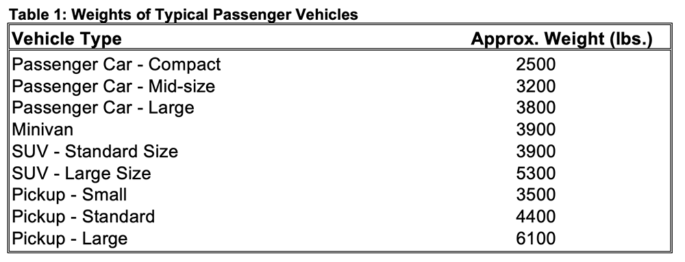
How much force does it take to stabilize a vehicle? That’s a question with many answers. If we are simply stabilizing a side-resting passenger vehicle in direct contact with flat ground, the answer is typically very little. However, if we intend to suspend or lift the vehicle, we potentially have a much different situation. We should be using additional tools meant for the lifting application which may be special jacks or lift bags and reserve the stabilization equipment for stabilization. If we use the same equipment for both applications, we have no backup. While lifting we should employ the “lift an inch, crib an inch” policy which is a simple task if we have a side wind type adjustment jack in our stabilization stand. If the lift bag fails, the stabilization equipment should at least have the capacity to support the weight of the vehicle. A chart (Table 1) is presented here with approximate passenger vehicle weight data for several classes of vehicles.
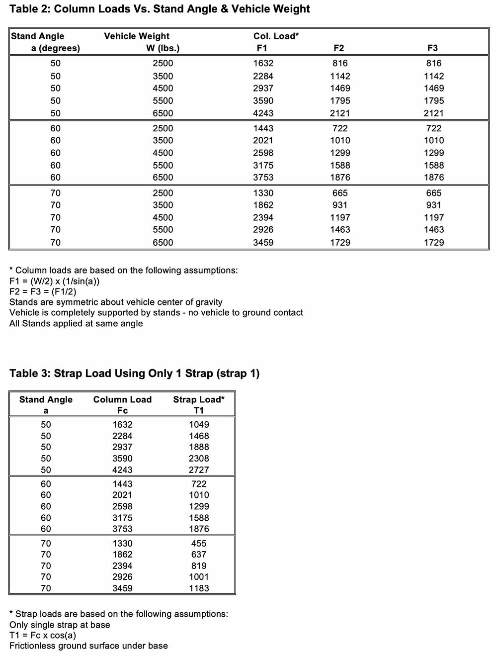
Using vehicle weight data in conjunction with a series of analytical relationships we can approximate compressive column loads in the stands and tensile forces in restraint strapping. Variables which will impact these forces in addition to the vehicle weight include the angle the stand is set at, the number of stands, the position of the stands relative to the vehicle center of gravity, the number of base restraint straps, and the angle between the base restraint straps if more than one strap is applied. To simplify this otherwise indeterminate problem, several approximations are made:
a. 100% of the vehicle weight is supported by the 3-point system
b. The stands are placed symmetrically about the vehicle center of gravity
c. The stands are all placed at the same angle (50, 60, or 70 degrees)
d. The ground is flat and frictionless (simulates a flat icy surface)
e. Straps are symmetric about the base
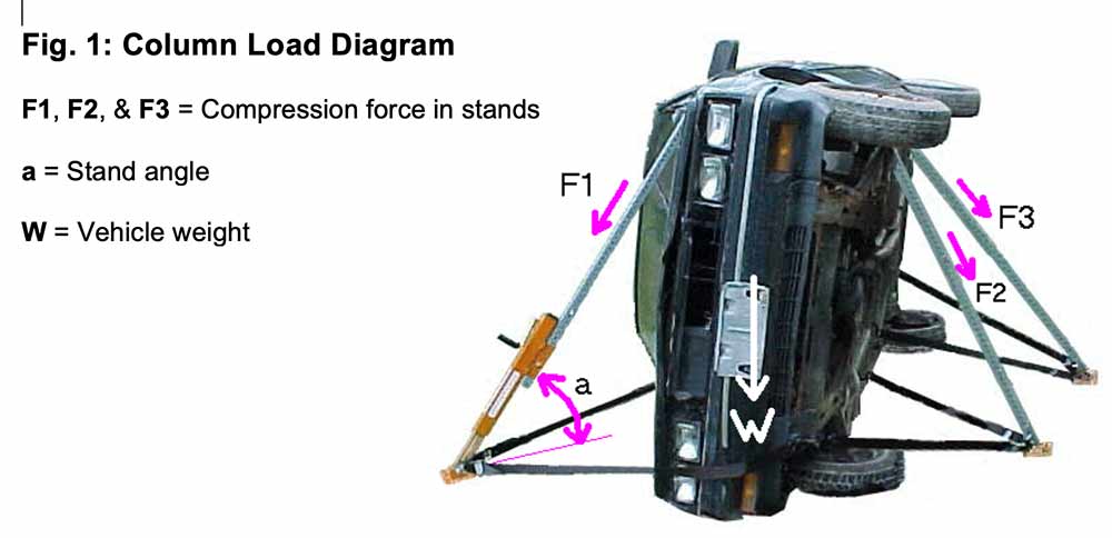
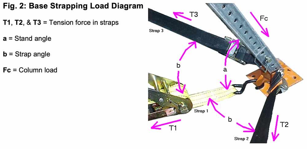
A diagram of a side-resting car (Fig. 1) shows the designation for the column loads and stand angles. A second diagram (Fig. 2) illustrates how the stand loads act to create tension in the base restraint strapping.
Example: Small pickup resting on its side
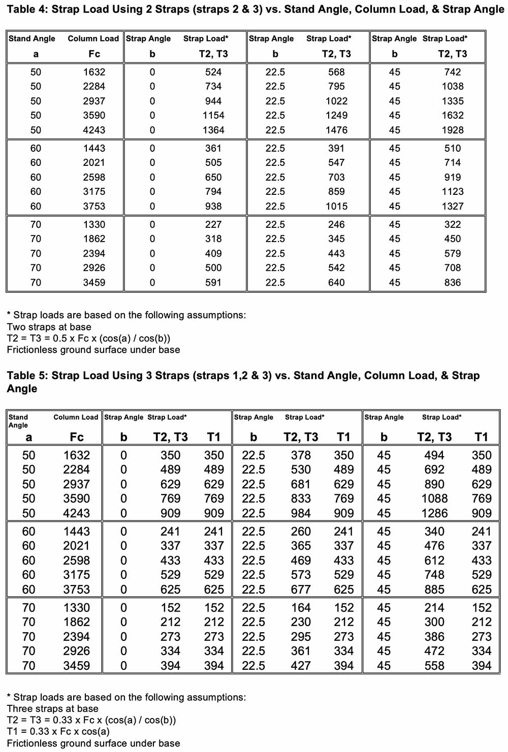
Let’s assume we have a small pickup involved in a single car accident. The pickup has rolled over and has come to rest on its side pinning the driver’s arm between the door and the ground. We intend to lift the pickup using lift bags to free the patient. What would be the approximate column loads in the stands and the tension loads in the straps assuming we stabilize the vehicle with a 3-point buttress setup and the lift bags fail? The ground is flat and icy. The stands are going to be set at 60 degrees. Each base will use 2 straps with a 45-degree angle between them.
Solution:
Using table 1, we can approximate the vehicle weight at 3500 lbs. In table 2 we see that a 3500-pound vehicle stabilized with 3 stands placed symmetrically about the vehicle’s center of gravity at a 60 degree angle results in stand 1 experiencing a column load of 2,021 lbs. and each of the other 2 stands experiencing a load of 1,010 lbs. From table 4, we see that a 2,021 lb. column load acting at 60 degrees results in a strap tension of 714 lbs. when 2 straps are used with a 45-degree angle between them. Note: the appropriate data is highlighted in the tables.
If you scan the tables, you will see how the different variables affect the stand and strap loads. A steeper stand results in lower column loads and thus lower strap tension. The more straps you incorporate the less tension in each strap. The wider the angle between straps for a base with two straps the greater the tension in the straps.
In the final segment of this series, we will look at stabilizing the roof-resting passenger vehicle. It is often a challenging task to properly stabilize the roof-resting vehicle and keep all extrication options open. However, we’ll introduce you to a unique new method that may revolutionize roof-resting stabilization.
If you would like additional information on the equipment used in this article, you may access the following web site: www.cepcotool.com or you may write to: Cepco Tool Company, Post Office Box 700, Spencer, NY 14883. © 2001, Cepco Tool Company.