バットレス・スタビライゼーション - Part II
今回は、バットレス安定化装置と技術に関する4部作のうちの第2部です。 前回は、機器の選択基準について説明し、サイドレスト付き乗用車のバットレス安定化のための3ポイント安定化技術を定義しました。 今回は、バットレスエンドフィッティング、ベースレストレスト、スタビライゼーションプロセスをサポートする様々なアクセサリについて説明します。
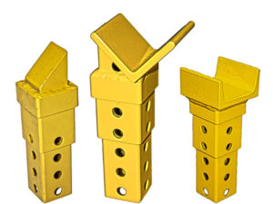
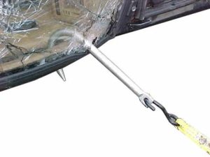
エンドフィッティングの選択
支柱の先端は、滑らないように、あるいは救助隊を驚かせないように、車両に噛み合わせる必要があります。 ヘッドが交換可能なシステムは、様々な構造物に柔軟に対応できます。 例えば、屋根の支柱の根元で購入する場合、端の金具は支柱を包み込むようにする必要があります。 外側の角には、角のある金具が適しています。 内側の角には、先の尖った金具を使用するのがよいでしょう。
操作中に支柱を移動させる必要がないように、先端の接触点を慎重に選択する必要があります。 構造的に問題のない場所を探します。 車の助手席側では、Aルーフとリアルーフの支柱の根元が購入ポイントになることがあります。 また、ボンネットの角やトランクの角など、乗員室に近い部分をはがすと、購入できる場合があります。 状況によっては、最後の手段として、パネルを切断して十分な購入ポイントを確保する必要があります。 フェンダーにある給油室や外灯の切り欠きなどのポケットは、適切な購入ポイントになる場合があります。 車体下部では、ロッカーパネルの下にあるロールリップやフロアパンの曲げ部分など、多くのオプションがあります。
ベース構造および拘束に関する考察
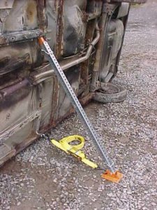
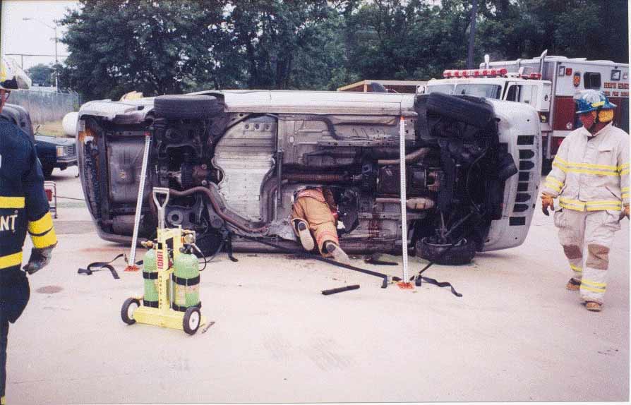
支柱の根元が動かないようにすることが必須です。 支柱の根元が車から滑り落ちないように抑えなければならない。 これは様々な方法で達成される。 ベースは、ベースが載っている面に固定するか、適切な強度のストラップやチェーンで車両に縛り付けるか、あるいは縛り付けと面への固定の両方を行うのがよいでしょう。 ベースの固定は、できるだけ地面に近い位置で車両に取り付ける必要があります。
 実用的でない場合を除き、各ベースに少なくとも2本のストラップを使用します。 2本のストラップを使用することで、ストラップと車体の接続部分を、プロップ先端のコンタクトポイントから独立させることができます。 通常、1本のラチェットストラップを使用する場合、例えばプロップチップ購入の真下に車両とのストラップ接続部があることを確認する必要があります。 そうしないと、ストラップを締めたときにベースが横に引っ張られ、スタンドが倒れる可能性があります。 2本のストラップを使用する場合は、より制約が少なくなります。 この場合、チップの位置はストラップの接続にあまり影響を与えません。 2本のストラップがベースから車体に向かって角度を持つのが理想的ですが、必ずしも同じ角度でなくてもかまいません。 2本のストラップの角度は45度から90度を選んでください。 ストラップ間の角度が大きいほど、ストラップにかかる負荷は大きくなります。 このストラップ構成は、ベースの外向きと横向きの両方の動きを制限します。 場合によっては、最適な、または唯一のストラップ購入方法が車両にまっすぐ戻ることであることに注意してください。 この場合でも、両方のストラップを接続する必要があります。
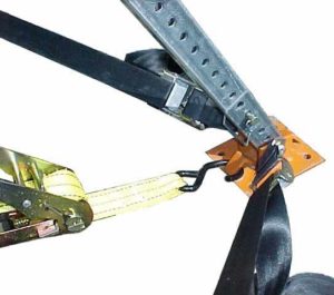
このベースには、あらかじめ2本のカムバックルストラップが接続されています。 このタイプのストラップは、素早く調整することができます。 このストラップを調整するには、単に手で弛みを引っ張るだけです。 カムバックルは、カムレバーを押さないとストラップが戻りません。 このタイプのストラップは、カムバックルストラップを手で締めることしかできないため、レスキュージャックシステムのサイドワインドジャックユニットのような締め付けや微調整が可能なシステムを使用することが必要です。 ジャッキを設置したスタンドとジャッキを設置していないスタンドが対向していると仮定すると、すべてのスタンドでジャッキがストラップの最終的な締め付けを行うことになります。 このため、ラチェットストラップを使用する必要がなく、その分時間がかかります。 ただし、ジャッキユニットなどの締め付け機構がない場合や、ジャッキユニットではスタンドのストラップを適切に締め付けられない場合は、ベースの中央にラチェットストラップをかけ、カムバックルストラップは単に冗長な拘束や安全性を付加する役割にとどめておくこともできます。 どのようなシステムであっても、ここで説明したような柔軟性を備えていれば、どのような状況にも対応できるはずです。
この記事の別の章では、さまざまな柱荷重、柱角度、ストラップの構成について、ベースストラップが受けるおおよその張力を示すいくつかの図表を紹介します。 シングル、ダブル、トリプルストラップベースのチャートが表示されます。 この式では、地面には摩擦がないものと仮定しています。つまり、ベースが滑ったり飛び出したりしないようにするために必要な力は、すべてストラップが担っていることになります。 これは、氷を扱う私たちにとって良い仮定です。 Res-Q-Jackのベースは、パラメータと荷重記号を特定するために図が使用されています。
 ストラップアクセサリー
 ストラップアクセサリー
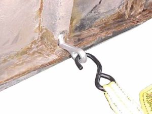
多くのストラップは、車両に取り付ける手段として「S」字フックを使用しています。 通常はこれで問題ないはずです。 ストラップを接続するための適切な場所を見つけるのが難しい場合があります。 ストラップのフックは、購入場所として最適なフレームスロットに入らない場合があります。 また、ルーフポストのようにストラップフックではつかめない大きさのものもあります。 また、屋根の支柱にストラップを巻き付けると、ストラップのウェビングが鋭利なガラスや金属に触れる可能性があり、好ましくない。 T字フックやJ字フックは、これらの問題を回避し、安定化のプロセスをさらにスピードアップします。 Tフックは、多くのフレームスロットとストラップフックの間のインターフェイスになります。 Jフックは、ルーフポストやフレームメンバーなどを容易につかむことができる大きなフックです。
地表面に関する考察
車体が乗っている路面の種類や状態も、安定させるための重要な要素です。 路面が傾斜している場合、3点支持では十分でない場合があります。 状況によっては、車両が滑らないように固定するための手段を追加で組み込む必要があるかもしれません。 プロップシステムによっては、軟弱地盤で支障をきたす場合があります。 点荷重を避けるために、プロップベースの下に幅の広い硬質パッドを使用する必要がある場合があります。 全く別の安定化手段が必要な場合もあります。
ネバーエンディングオペレーション
スタビライゼーションは作戦中も続く。 Firehouse Expoのクラスで、Ron Mooreが「安定化はMVA作業中に決して終わらない任務の一つである」と言ったのは、このことをうまく表現しています。 救出作業中、事故車の特性は変化します。 救助隊員や装備の追加、車両部品の取り外しが行われると、車両の重量が変化し、重心が移動する。 ドアが取り外されたり、ルーフの支柱が切断されたり、ガラスが割れたりすると、すでに損なわれていた車両の構造的完全性が変化する。 車両のルーフと支柱は、事実上トラス構造になっています。 これらを取り外すと、車両の剛性は著しく低下します。 車両の救助活動中は、安定化コンポーネントを監視する必要があります。 ベースレストを調整したり、購入ポイントを変更したり、安定化素材を追加したりする必要があるかもしれません。 切断工具を操作する者は、切断工具が安定化に与える影響を認識し、支柱やベースストラップで固定されている部材を取り外さないように注意しなければならない。 安定化部材を監視し、潜在的な問題を他の人に知らせるために、チームメンバーを指名する必要があります。
基本ガイドライン
ここでは、平地でのサイドレストカーを安定させるための基本的な指針を紹介します。
- バットレスシステムをセットアップしている間、車両をコントロールするために手動で安定させたり、ウェッジを置いたりします。
- 状況、患者の位置、車のタイプや状態、障害物などに基づいて、ジャッキスタンド1本を置くのは車のどちら側か、3ポイントセットアップを使用する場合は2本の調節可能なスタンドを置くのはどちら側かを決定します。
- 二人一組で作業する。 1人はスタンドの調整、セッティングをしているメンバーの手の届く範囲でトラブルを監視する。
- まず、車両の最も不安定な側にスタンドをセットし、次に反対側を作業してください。
- できるだけ先端を高くして車両に装着してください。 ベースストラップはできるだけ低い位置に取り付けてください。 スタンドの傾きは50~70度にしてください。
- すべてのスタンドが配置されたら、システムを締め付けます。 ストラップとチップの噛み合わせがしっかりしていることを確認します。 必要であれば調整します。
- 機器の稼働状況を監視し、必要に応じて調整を行う。
MVAの状況はすべて異なる。 繰り返しになりますが、ロン・ムーアが言うように、"安定化の効果は、チームの道具に対する経験、工夫、機械的知識、事故の性質、そして沈没船を読み取る能力に集約される "のです。 次回は、支柱の圧縮荷重と、ストラップの引張力について見ていきます。
この記事で使用した機器に関する追加情報をご希望の場合は、次の Web サイトにアクセスしてください: www.cepcotool.com または、次の宛先まで書面にてご連絡ください。Cepco Tool Company, Post Office Box 700, Spencer, NY 14883.© 2001, Cepco Tool Company.